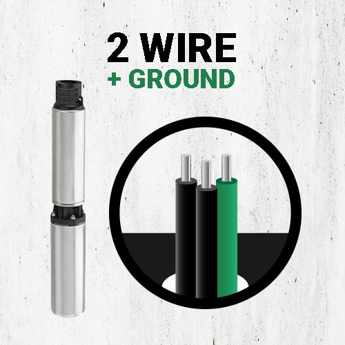
Test 2 Wire Submersible Well Pump
2 wire submersible well pump wiring diagram a newbie s overview of circuit diagrams.
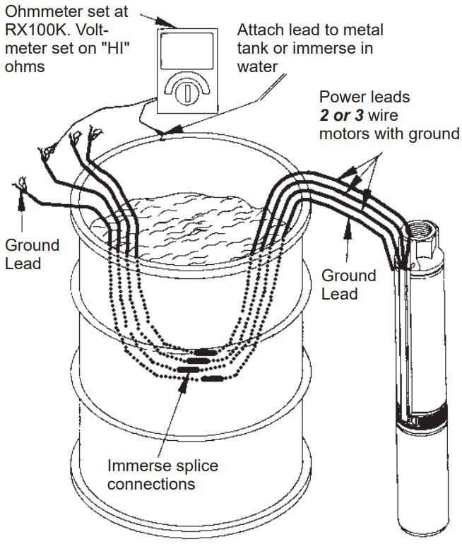
Test 2 wire submersible well pump. Getting from point a to point b. Turn off the well s circuit breaker. Tests of the pump wiring are made by individually connecting between each wire at the well head and ground. On 3 wire motors measure the resistance of yellow to black main winding and yellow to red start winding.
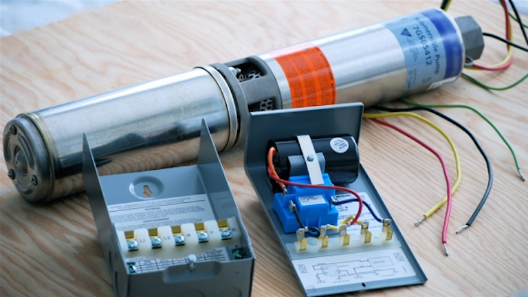
The control box mounts to a wall next to the well s water storage tank. The purpose is the very same. The correct circuit breaker has a well label. I usually test for ampere draw at the wires at the well cap.
How to test a well pump control box step 1. Testing a franklin electric qd quick disconnect box qd boxes are designed for use with 3 wire single phase submersible motors from. Sometimes it s at the circuit panel or at the controller if there is one. Use next scale up for values over 10 ohms.
If the well casing is metal then connect the ground lead of the vom dmm be sure it s a good clean connection to the well casing or metal piping. Literally a circuit is the path that enables electrical power to. Inspect the control box s wiring diagram. Measure the resistance from line to line.
Open the control box s lid. Most of the 2 wire 3 4 hp submersible pumps around here draw about 9 to11 amps at 220 to 240v. Bench testing a submersible pump for continuity and or short with volt ohm meter. It shows the parts of the circuit as streamlined shapes and also the power and also signal connections between the devices.
In this video i go over the differences of a 2 wire and a 3 wire submersible well pump this is associated with the starting components for the pump and whet. A very first look at a circuit layout could be complicated however if you can review a subway map you could read schematics. There is usually a tag or decal on or near the well cap with pump motor specs. Troubleshooting inside the box is made simple by the control components automatically disconnecting from the system when the lid is removed.
A wiring diagram is a simplified standard pictorial representation of an electric circuit.

Water Pump Wiring Troubleshooting Repair Pump Wiring Diagrams

2 Wire Vs 3 Wire Well Pump Motors Youtube

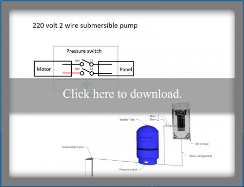
Wiring Diagram For 220 Volt Submersible Pump Bookingritzcarlton Info Well Pump Well Pump Pressure Switch Submersible Well Pump

Wiring Diagram For 220 Volt Submersible Pump Http Bookingritzcarlton Info Wiring Diagram For 220 V Well Pump Pressure Switch Submersible Well Pump Well Pump
How To Install And Wire A Well Pump Well Pump Installation Guide
Troubleshooting Residential Submersible Pump Systems Ec M
Everbilt 1 Hp Submersible 2 Wire Motor 10 Gpm Deep Well Potable Water Pump Efsub10 122hd The Home Depot
Submersible Well Pump Wiring Diagrams Lovetoknow

Submersible Pump Control Box Wiring Diagram For 3 Wire Single Phase Submersible Pump Electrical Circuit Diagram Well Pump

Square D Well Pump Pressure Switch Wiring Diagram Welcome To Be Able To My Website With This Time Well Pump Pressure Switch Submersible Well Pump Well Pump

3 Wire Vs 4 Wire Submersible Pump Doityourself Com Community Forums

2 Wire Vs 3 Wire Submersible Well Pumps Youtube

Franklin Electric 2445089003 1 Hp Submersible Motor

Wiring Diagram For 220 Volt Submersible Pump Bookingritzcarlton Info Well Pump Submersible Pump Submersible Well Pump

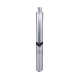
Goulds 5gs07422c 5gpm 3 4hp 230v 2 Wire 4 Stainless Steel Submersible Well Pump
Differences Between 2 Wire And 3 Wire Well Pumps Deep Well Pump Wiring Explained

Goulds 10sb10422c 10 Gpm 1 Hp 230 V 2 Wire Submersible Well Pump Amazon Com Industrial Scientific

2 Wire With Ground 12 Gauge Twisted Submersible Pump Wire
2 Vs 3 Wire Well Pump Terry Love Plumbing Advice Remodel Diy Professional Forum

Happybuy Well Pump 1 5 Hp 220v Submersible Well Pump 335ft Head 24gpm Stainless Steel Deep Well Pump For Industrial And Home Use Amazon Com

Goulds 7hs10422c 7gpm 1hp 230v 2 Wire 4 Hs Series Submersible Well Pump

Submersible Well Pump Installation Troubleshooting Submersible Well Pump Well Pump Pressure Tanks
115 Volts Or 220 Volts To Well Pump Terry Love Plumbing Advice Remodel Diy Professional Forum

Red Lion Rl12g10 2w2v 1 Hp 12 Gpm 2 Wire 230 Volt Submersible Deep Well Pump Sump Pumps Amazon Com
Https Encrypted Tbn0 Gstatic Com Images Q Tbn 3aand9gcqdh7qpbj Krifjg1ulbd3aocgx9qtvfu4qokdalha Usqp Cau
Myers Myers 2nfl52 8 P4 Submersible Stainless Steel Pump 8 Gpm 0 5 Hp 230v 2 Wire 1ph Myr2nfl528p4

Grundfos 5sq05 90 230v 5gpm 1 2hp 230v 2 Wire 96160130 3 Stainless Steel Submersible Well Pump
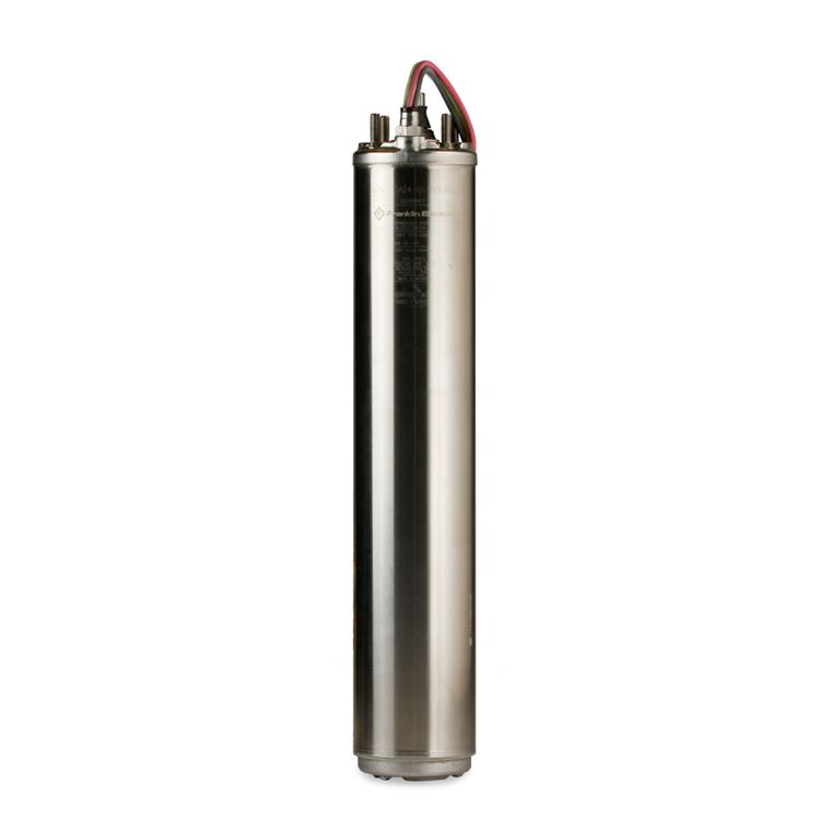
Franklin Electric Franklin Electric Fps 4400 Tri Seal 10fa05p4 2w230 Submersible Well Pump Motor 10 Gpm 0 5 Hp 230v 1ph 2 Wire Fec93781010
Https Www Hallmarkind Com Catalogs Deep Well Pumps Pdf
Flotec Fp2212 12 Flotec Fp2212 10 Gpm 1 2 Hp Deep Well Submersible Pump 2 Wire 230v
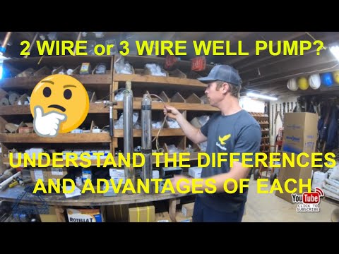
2 Wire And 3 Wire Submersible Well Pump Motor Wiring Differences Explained Youtube
7 Things Every Well Pump Owner Should Know Youtube

Shop For 3 Inch Submersible Well Pump On Zoro Com

Pentair Sta Rite Hs Series Stainless Steel 4 Submersible Pumps Sta Rite Water Supply Professional Water Movement
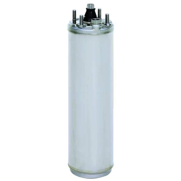
Franklin Electric 2445089003s 630 94 Subm Pump Mtr 1 Ph 1 Hp 230v 4 In 2 Wire Zoro Com

Dayton 1lzv4 674 59 Pump Deep Well 2 Wire 20gpm 1 Hp 230v Zoro Com
Electric Water Motor 2 Wire Single Phase Water Motor
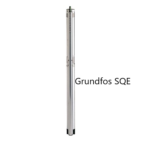
Grundfos 3 Sqe Series 10 Gpm 3 4 Hp 230volt 2 Wire Deep Well Submersible

Myers 2st52 12plus P4 1 2 Hp Submersible Well Pump 230 Volt 2 Wire 12 Gpm

Eco Flo Efsub7 122 3 4 Hp 2 Wire 4 Submersible Well Pump Walmart Com Walmart Com

Gm 0692 2wire Submersible Well Pump Wiring Diagram Franklin Well Pump Wiring Download Diagram
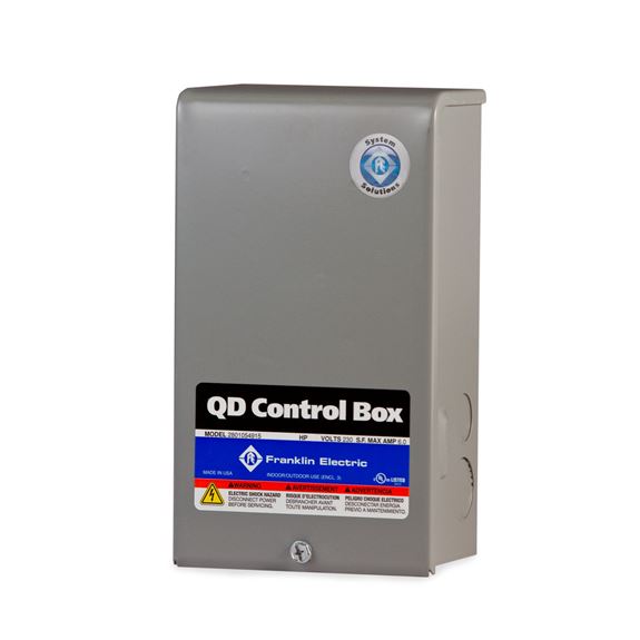
Franklin Electric Franklin Electric 2801044915 Qd Submersible Motor Control Box 0 5 Hp 115v 1ph For 3 Wire Motors Fec2801044915
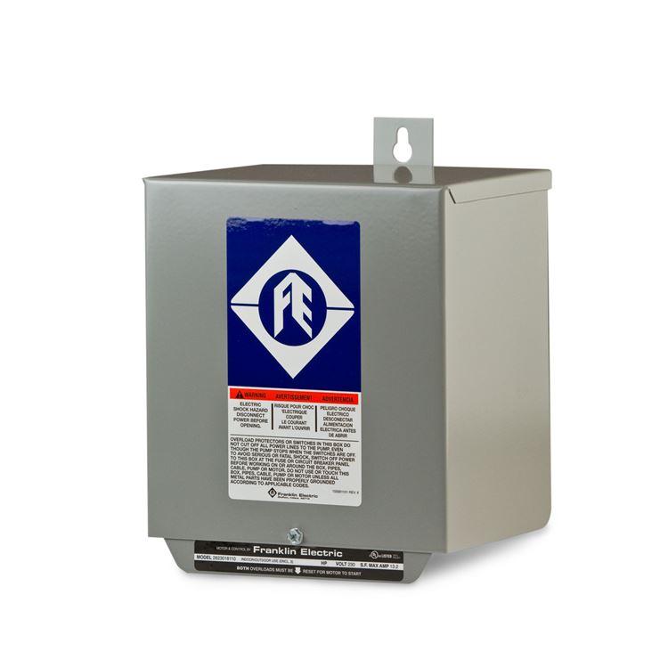
5 Hp Franklin Electric Submersible Well Pump Motor Control Box
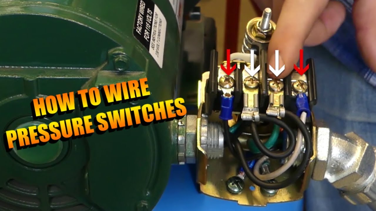
How To Wire A Pressure Switch Youtube
All 4 Submersible Pumps

How To Troubleshoot Submersible Motors With Your Ohmmeter Youtube

Grundfos 15sq07 180 230v 15gpm 3 4hp 230v 2 Wire 96160149 3 Stainless Steel Submersible Well Pumps
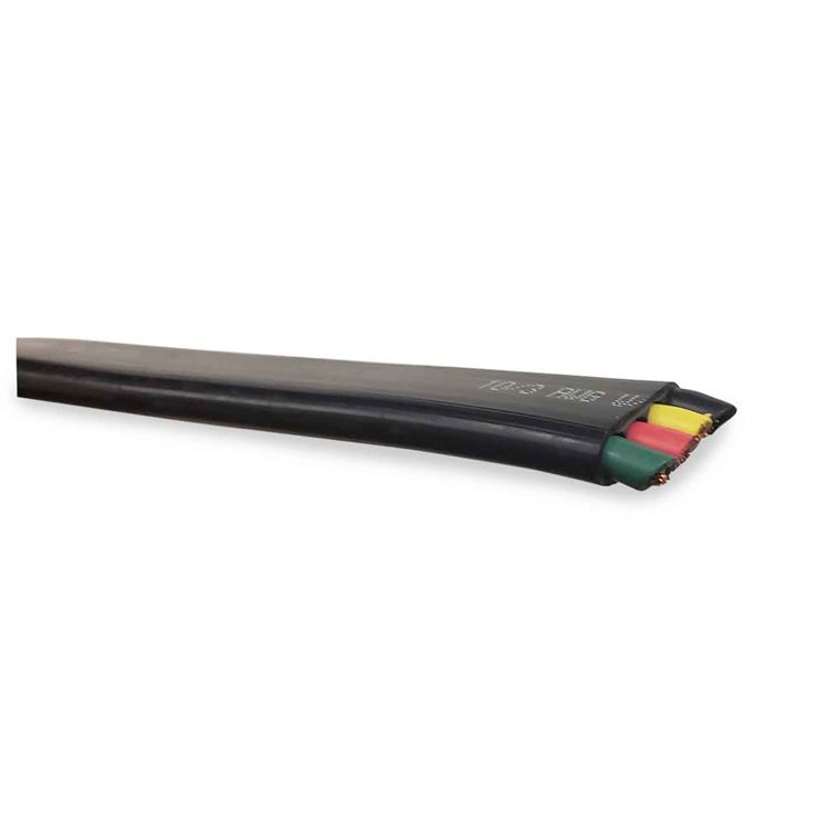
6 3 Electrical Wire Submersible Well Pump Wire R C Worst Co
